-
DP connects
organizations of all kinds with
the world's leading CAD Experts. -
Our Clients :


-
We are a member of :


- DP Associates Inc.


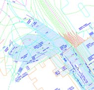
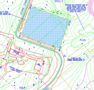
Contour Mapping
Contour lines are used to join a succession of points of identical elevation. They are used to demonstrate topography or relief on a map. They help in confirming the height of ground above Mean Sea Level in either feet or meters.Topographic maps make use of contour lines to specify the nature and altitude of these landscape features. It is not very easy to show three-dimensional objects, like hills and valleys, on a two-dimensional surface, like a map. Contour lines are lines that connect the positions of equal measures of elevation.
Contour-mapping is the depiction of landscapes and topography for an area that has various altitudinal differences in its contour (e.g. valleys, hills, or plains). A 2D contour-map can be confusing and difficult to understand, so some people prefer to use a 3D CAD model instead. A CAD 3D model of a contour map is a helpful tool for power and energy companies including architects, engineering firms and real estate contractors.
Contour maps are used in construction projects for assessing the varying ground levels and how they should be levelled for constructing a building. The benefits of using 3D CAD contour maps are:
Contour mapping/Map digitization by Design Presentation is of the highest quality and is surprisingly affordable. You can view some of our contour mapping samples.
Send us the details of your contour mapping project (via email or fax) and we will get back to you with a free quotation.
Contour Mapping (Portfolio Samples)
 |
 |
www.photostouchup.com | www.dp-architecturaldrawings.biz | www.dpaincorporated.com | www.autocaddesign.biz | www.autocadarchitectural.com | www.draftingdesign.biz
www.dp-draftingservices.com | www.formatconversion.biz | www.mechanicaldrawings.biz | www.rastertovector.biz | www.designpresentation.co.uk
www.design-presentation.com | www.designpresentation.net
www.dp-draftingservices.com | www.formatconversion.biz | www.mechanicaldrawings.biz | www.rastertovector.biz | www.designpresentation.co.uk
www.design-presentation.com | www.designpresentation.net
DesignPresentation Associates, Inc. Unauthorised use not permitted.